Electronic circuit simulation

General FreeBASIC programming questions.
Post Reply
badidea
Posts: 2591
Joined: May 24, 2007 22:10
Location: The Netherlands

Electronic circuit simulation

Post by badidea »

Hello all (electronics enthusiasts), I am trying to simulate a relative simple circuit (see drawing in code). The result seems plausible. Anyone who wants to check the calculation steps?

Code: Select all

' Circuit:
'
'    +---(L1)---+---(L2)---+
'    |          |          |
'    |          |          |
'   (Us)       (C1)       (R1)
'    |          |          |
'    |          |          |
'    +----------+----------+
'
' Inductor:  U = L * dI / dt  or  dI = U * dt / L
'
' Capacitor: I = C * dU / dt  or  dU = I * dt / C
'
' Resistor: U = I * R

'known/set values
dim as double Us = 200 'V (power supply)
dim as double L1 = 320 * 1e-6 'H
dim as double L2 = 100 * 1e-6 'H
dim as double C1 = 10 * 1e-6 'F
dim as double R1 = 1.0 'Ohm

'to be calculated / intermediate values
dim as double U_L1, U_C1, U_L2, U_R1 'V
dim as double I_L1, I_C1, I_L2, I_R1 'A
dim as double dU_L1, dU_C1, dU_L2, dU_R1 'U
dim as double dI_L1, dI_C1, dI_L2, dI_R1 'A

'simulation time settings
dim as double t = 0, tEnd = 2e-3 's
dim as double dt = (tEnd - t) / 10000 's

const W = 800, H = 600
screenres W, H, 32
width W \ 8, H \ 16

'iterate over time
while t < tEnd
	'step 1, determine I_L1
	U_L1 = Us - U_C1
	dI_L1 = U_L1 * dt / L1
	I_L1 += dI_L1
	'step 2, determine U_C1
	I_C1 = I_L1 - I_L2
	dU_C1 = I_C1 * dt / C1
	U_C1 += dU_C1
	'step 3, determine U_R1
	I_R1 = I_L2
	U_R1 = I_R1 * R1
	'step 4, determine I_L2
	U_L2 = U_C1 - U_R1
	dI_L2 = U_L2 * dt / L2
	I_L2 += dI_L2
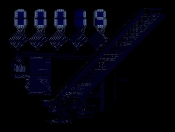
	'plot at top: Voltages
	pset((t / tEnd) * (W - 20) + 10, H * 0.4 - Us), rgb(0, 0, 255) 
	pset((t / tEnd) * (W - 20) + 10, H * 0.4 - U_C1), rgb(0, 255, 0) 
	pset((t / tEnd) * (W - 20) + 10, H * 0.4 - U_R1), rgb(255, 0, 0)
	'plot at bottom: Currents
	pset((t / tEnd) * (W - 20) + 10, H * 0.9 - I_L1), rgb(0, 0, 255) 
	pset((t / tEnd) * (W - 20) + 10, H * 0.9 - I_C1), rgb(0, 255, 0) 
	pset((t / tEnd) * (W - 20) + 10, H * 0.9 - I_L2), rgb(255, 0, 0)
	'update time
	t += dt
wend

'display what is what
draw string (10, 10), "Us (blue), U_C1 (green), U_R1 (red)"
draw string (10, H - 30), "I_L1 (blue), I_C1 (green), I_L2 (red)"

'show I_R1 end value
draw string (W \ 2, H \ 2), "I_R1 [A] = " + str(I_R1)

'wait until key press
while inkey = "" : wend
paul doe
Moderator
Posts: 1733
Joined: Jul 25, 2017 17:22
Location: Argentina

Re: Electronic circuit simulation

Post by paul doe »

One amazing cellular automata that simulates electronic circuits is Wireworld. Here's my implementation in FreeBasic to play with:

https://github.com/glasyalabolas/fb-wireworld

Image

Included is the Wireworld computer that computes prime numbers. It may take a while to output one, but that depends mostly on your hardware. Electronics is quite a fascinating topic, indeed ;)
BasicCoder2
Posts: 3906
Joined: Jan 01, 2009 7:03
Location: Australia

Re: Electronic circuit simulation

Post by BasicCoder2 »

deleted.
Last edited by BasicCoder2 on Apr 17, 2019 13:09, edited 1 time in total.
fxm
Moderator
Posts: 12110
Joined: Apr 22, 2009 12:46
Location: Paris suburbs, FRANCE

Re: Electronic circuit simulation

Post by fxm »

badidea wrote:The result seems plausible. Anyone who wants to check the calculation steps?
It seems to be good.
badidea
Posts: 2591
Joined: May 24, 2007 22:10
Location: The Netherlands

Re: Electronic circuit simulation

Post by badidea »

fxm wrote:
badidea wrote:The result seems plausible. Anyone who wants to check the calculation steps?
It seems to be good.
Thanks, I checked the result with LTspice. Looked the same.
I am going to add more stuff (that I don't know how to do in LTspice).
Post Reply