cnc

General FreeBASIC programming questions.
Turd
Posts: 175
Joined: Aug 31, 2007 23:34
Location: Saskatchewan, Canada

Post by Turd »

I changed it but it still doesn't work.

Code: Select all

dim as integer i

shell "stty -F /dev/ttyS0 speed 9600"
sleep 1000
if open com( "/dev/ttyS0:9600,n,8,1,cs0,cd0,ds0,rs" as #1 ) <> 0 then
  locate 1, 1
  print "Unable to open com port"
  end
end if

sleep 2000

do
	print #1, &b00100010; &b00000010;
	sleep 100
	print #1, &b01000100; &b00000100;
	sleep 100
	print #1, &b00010001; &b00000001;
	sleep 100
	print #1, &b10001000; &b00001000;
	sleep 100
loop
I have a logic analyzer connected to it:
Image
phishguy wrote: BTW - your CNC platform looks pretty cool. Did you build it from plans, or did you design it yourself? I've always wanted to build one. But, I've never had the time, money, or fabricating equipment and skills.
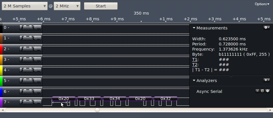
I built it from scratch, I got ideas from what I've seen online.
I have all the specks for each piece if you want them. It might take a bit to get them all organised though lol.
Dinosaur wrote:Hi all

It looks like you are timing and switching each phase changeover.
My experience with trying to switch the phases on the stepper motor;
1:You spent to much cpu time timing and controlling the phases.
2:You can't achieve the speed of rotation.
3:Resolution of Timing isn't good enough for smooth operation.

So, I would get a very cheap stepper board like this one
http://www.oceancontrols.com.au/KTA-179.html
which doesn't need the massive heatsinks.(unless that is your power supply) I use a similar motor
http://www.oceancontrols.com.au/MOT-128.html with the above board.

Then use the serial port with the PicAxe or other PIC and let the it do the clocking for speed only. So, tell the PIC "Motor(n) , Fwd, speed, Nbr of steps"

You can then use the PC to calculate the trajectory and update the pic via serial, allowing an acceleration curve as well as a decelleration.

Let the mundane job of phase control be done by a dedicated chip/board.

Regards
Thats kind of what I'd like to do. Right now I'm trying to get FB to talk to the PICAXE. I'd like for the PICAXE to use a line algorithm and just receive coordinates.
Turd
Posts: 175
Joined: Aug 31, 2007 23:34
Location: Saskatchewan, Canada

Post by Turd »

Dinosaur wrote:So, I would get a very cheap stepper board like this one
http://www.oceancontrols.com.au/KTA-179.html
which doesn't need the massive heatsinks.(unless that is your power supply) I use a similar motor
http://www.oceancontrols.com.au/MOT-128.html with the above board.
phishguy wrote:I would have to agree with Dinosaur that a 2 or 3 axis stepper control board would be a better way to go. If you still want to develop that portion on your own, I would suggest looking at a different micro such as a Parallax Propeller. There have been several hobbyists out there that have developed CNC controllers using this micro. However, off the shelf controllers would make the development time much quicker.
That looks to be a bit to expensive for me.
I'm using these motors:
http://www.hvwtech.com/products_view.as ... ctID=10948
And these motor drivers:
http://www.hvwtech.com/products_view.asp?ProductID=343
MichaelW
Posts: 3500
Joined: May 16, 2006 22:34
Location: USA

Post by MichaelW »

It seems to me that a recent fast, multi-core PC running the right code could do very precise, very low-level control of multiple motors. You would have the capability of running the code for each motor/axis on a dedicated core, running at a very high clock speed, and without interruptions.
Last edited by MichaelW on Oct 02, 2011 0:04, edited 1 time in total.
Turd
Posts: 175
Joined: Aug 31, 2007 23:34
Location: Saskatchewan, Canada

Post by Turd »

I got it working.

Code: Select all

dim as integer i

shell "stty -F /dev/ttyS0 speed 9600"
sleep 1000
if open com( "/dev/ttyS0:9600,n,8,1,cs0,cd0,ds0,rs" as #1 ) <> 0 then
  locate 1, 1
  print "Unable to open com port"
  end
end if

sleep 2000


do
	print #1, chr(34, 2);
	sleep 10
	print #1, chr(68, 4);
	sleep 10
	print #1, chr(17, 1);
	sleep 10
	print #1, chr(136, 8);
	sleep 10
loop
or

Code: Select all

dim as integer i

shell "stty -F /dev/ttyS0 speed 9600"
sleep 1000
if open com( "/dev/ttyS0:9600,n,8,1,cs0,cd0,ds0,rs" as #1 ) <> 0 then
  locate 1, 1
  print "Unable to open com port"
  end
end if

sleep 2000


do
	print #1, chr(&b00100010, &b00000010);
	sleep 10
	print #1, chr(&b01000100, &b00000100);
	sleep 10
	print #1, chr(&b00010001, &b00000001);
	sleep 10
	print #1, chr(&b10001000, &b00001000);
	sleep 10
loop
Weird.
Last edited by Turd on Oct 02, 2011 0:50, edited 1 time in total.
Turd
Posts: 175
Joined: Aug 31, 2007 23:34
Location: Saskatchewan, Canada

Post by Turd »

MichaelW wrote:It seems to me that a recent fast, multi-core PC running the right code could do very precise, very low-level control of multiple motors. You would have the capability of running the code for each motor/axis on a dedicated core, running at a very high clock speed, and without interruptions.
Sounds cool but I've got just the one core.
phishguy
Posts: 1201
Joined: May 05, 2006 16:12
Location: West Richland, Wa

Post by phishguy »

The propeller board USB is only $29.99 and would make an ideal platform for a multi axis stepper controller.
http://www.parallax.com/Store/Microcont ... fault.aspx
vladimir777
Posts: 94
Joined: Aug 19, 2011 18:28

Post by vladimir777 »

If you are using win2000+ then you have to use

inpout32.dll search net or even this forum and you will find info

Code: Select all

#ifdef __FB_DOS__
	Function PORT_IN (ByVal PortAddress As short) As short
		PORT_IN =inp(PortAddress)
	End Function
	Sub PORT_OUT (ByVal PortAddress As short, ByVal Value As short)
		out (PortAddress, Value)
	End Sub
#endif

#ifdef __FB_WIN32__
	Declare Function PORT_IN Lib "inpout32.dll" Alias "Inp32" (ByVal PortAddress As short) As short
	Declare Sub PORT_OUT Lib "inpout32.dll" Alias "Out32" (ByVal PortAddress As short, ByVal Value As short)
#endif

I looked over your timing routines. To so one step you have to:
1. set direction pins first
2. set step pins: 1 if you are stepping, 0 if not
3. wait at least 200 nanosec for most stepdrivers
4. bring down to 0 all step pins
5. then wait calculated time

if your stepdrive has 1600 microsteps per revolution, and your speed is let say 1inch/sec time is 1/1600 sec - have to make function to calculate wait time for choosen speed
-----------------------------------------------------------------
Then win2000 is doing MUCH BETTER job than XP

To do this properly you will have to have rampup and rampdown routines, because nothing can accelerate from 0 to SPEED in no time

It could be linear acceleration, but over time I have found quater circle or quater sine function are way better

By not having rampup routine your stepper will loose steps. I have seen a guy trying to cut mosaic into his hardwood floor and his start and end point was half inch different - so he had to replace floor :)

or use

http://www.warp9td.com/ 155 $

or

use ARDUINO it is cheap 30$ and here you can find source code for arduino

http://reprap.org/wiki/Main_Page

Their routines for lines and circles are not that bad - through serial port you send GCODE programs. but G42 G41 and G40 - offset are not implemented. so when you are drawing in AUTOCAD or so you will have to offset all polylines, circles etc

And next time if you are using different routerbits with different diameter, you will have to remake GCODE program

Or use: http://www.linuxcnc.org/ site down or
http://www.dakeng.com/turbo.html
It is written in TP3 for DOS

For more info regarding CNC machine building visit
http://www.cnczone.com

====================================
Lachie Dazdarian
Posts: 2338
Joined: May 31, 2005 9:59
Location: Croatia
Contact:

Post by Lachie Dazdarian »

Fascinating topic. I'm ashamed to admit that I never dabbled with this, despite being a CNC machines programmer and technologist. Hrm...
marcov
Posts: 3462
Joined: Jun 16, 2005 9:45
Location: Netherlands
Contact:

Post by marcov »

I use a motorcontrol pic (microchip dspic33f an -e series).

8 motorcontrol channels that can be driven at 20 MHz (more (14) and higher(up to 60MHz) for the -e series), and in the Eur 5-10 range.

The motor control I do is very, very limited (just let one simple motor spin), but I do use the motor control periphals a lot to drive flash lights with a parameterisable duty cycle.

The parts are a bit hard to solder (but my boss can do it and says anybody with a bit of serious soldering experience can do it after a few failed tries), but cheap and very, very powerful.

There might be third party offerings of experimentation boards under Eur 50 with such part on it, very, very nice.

(I assume there are LPC ARM versions too, I just know microchip best)

Moral of this story, try to find parts with motorcontrol periphery, and don't program it yourself. The periphery can go much and much faster, and usually has all kinds of additional options (e.g. synchronizing with external signals as clock, like e.g. a quadrature encoder).

The remaining CPU can then be easily and fully for e.g. shift registers, buffering the instructions (from serial, or in my case, CAN) etc.
Post Reply